We hope everybody had a good April break. It’s nice to have a little time off before the final push to the end of the year. Students are back in shop and ready to keep moving their projects forward. For our seniors, this is their last month in the shop, so they have a lot to do before they move on to new things!
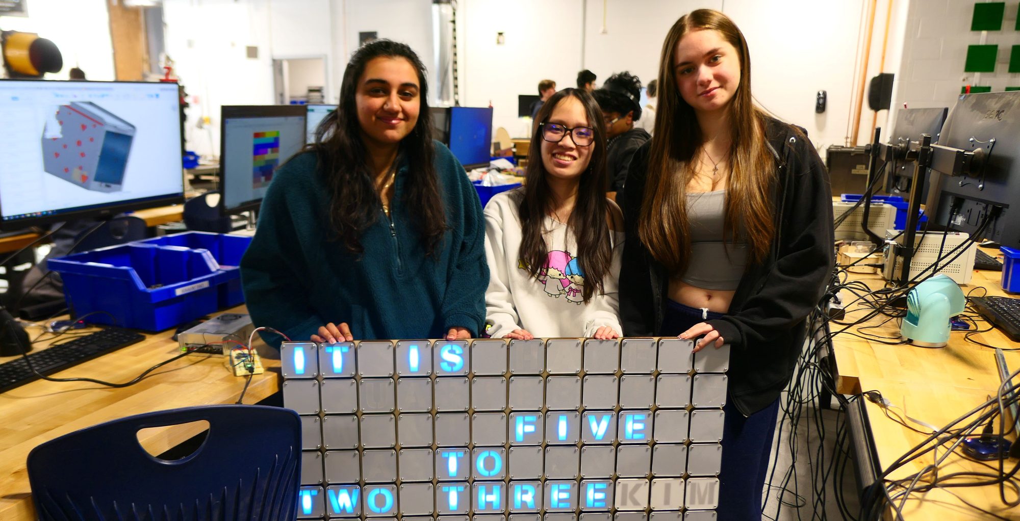
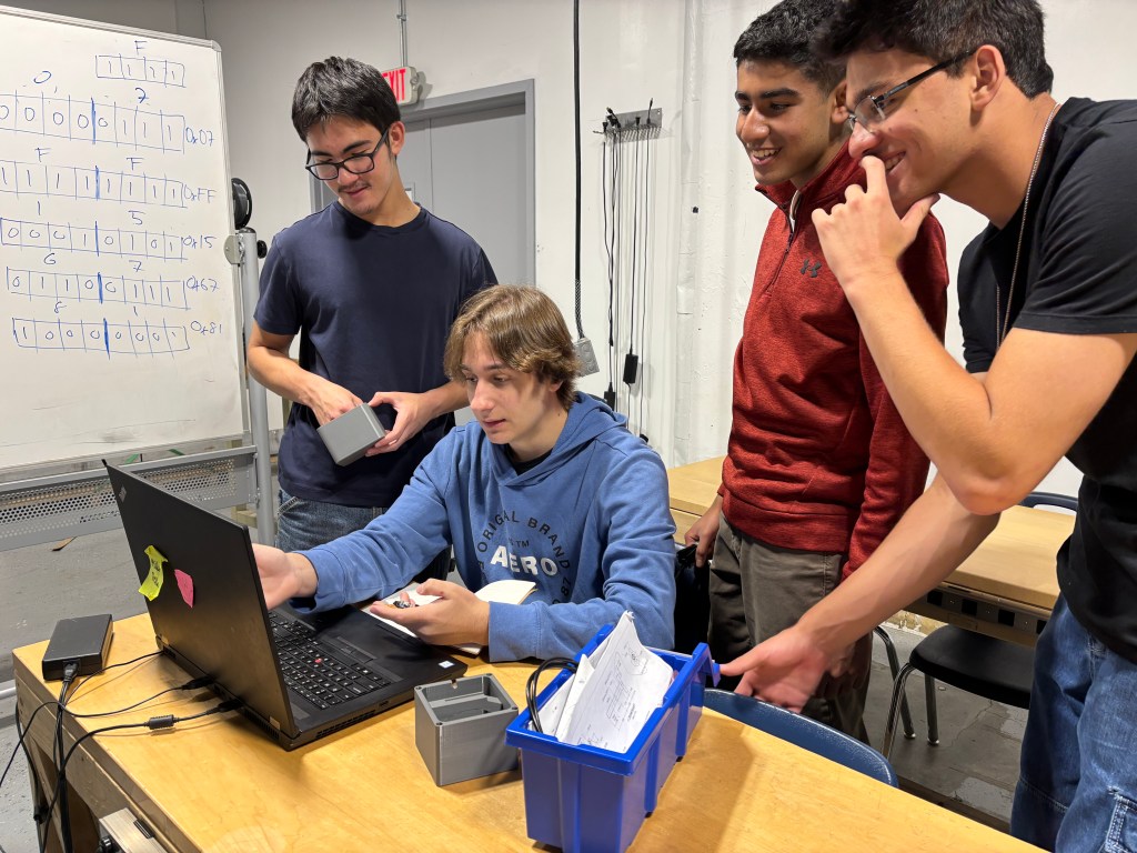
Let’s get started with some of the work happening last week. Senior Kim Dao ’26 was finishing up the Large Word Clock Project:
This week I was working on the word clock and we received the new ring terminals and metal brackets. Monday was when I installed ring terminals with Bella and Jaspreet. Jaspreet and Bella both drilled in the new metal brackets from Metal Fab. The frame turned out to be much more sturdier. Now with the new ring terminals, we were able to screw them into the metal bar. We tested the connections and made found out that the wires from the power supply wasn’t working. I figured that it must have been the difference between the wires we used to crimp onto. I swapped the original, single, to multi-strands.
After fixing that issue on Tuesday, all the connections worked. We decided to test the power through finally turning the power supply on. However, the lights were not turning on and I thought it was a problem with the ESP32 board. This day was when the shop was having router issues and thus the board couldn’t connect to the WiFi which was the main reason why the LEDs never turned on.
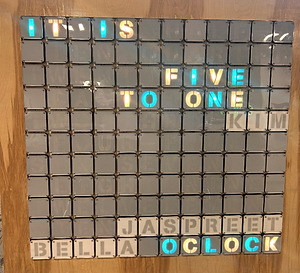
On Wednesday, I was able to turn on the power supply and see the LEDs turn on. However, when I tried to change the color on the web server, it didn’t work. I was confused and thought I had the wrong address. I asked Mr. Christy about the issue and he explained that the address for the web server must have changed because previously it wasn’t registered/saved. The new address was given to me and I was freely able to change the colors. This day I also worked on finishing the hinges on my jewelry box.
Thursday, I continued to work on my hinges and was able to make more changes to the box itself. I added another slot for the acrylic to go into the top of the box. This should allow a more easier glue time and strong structure.
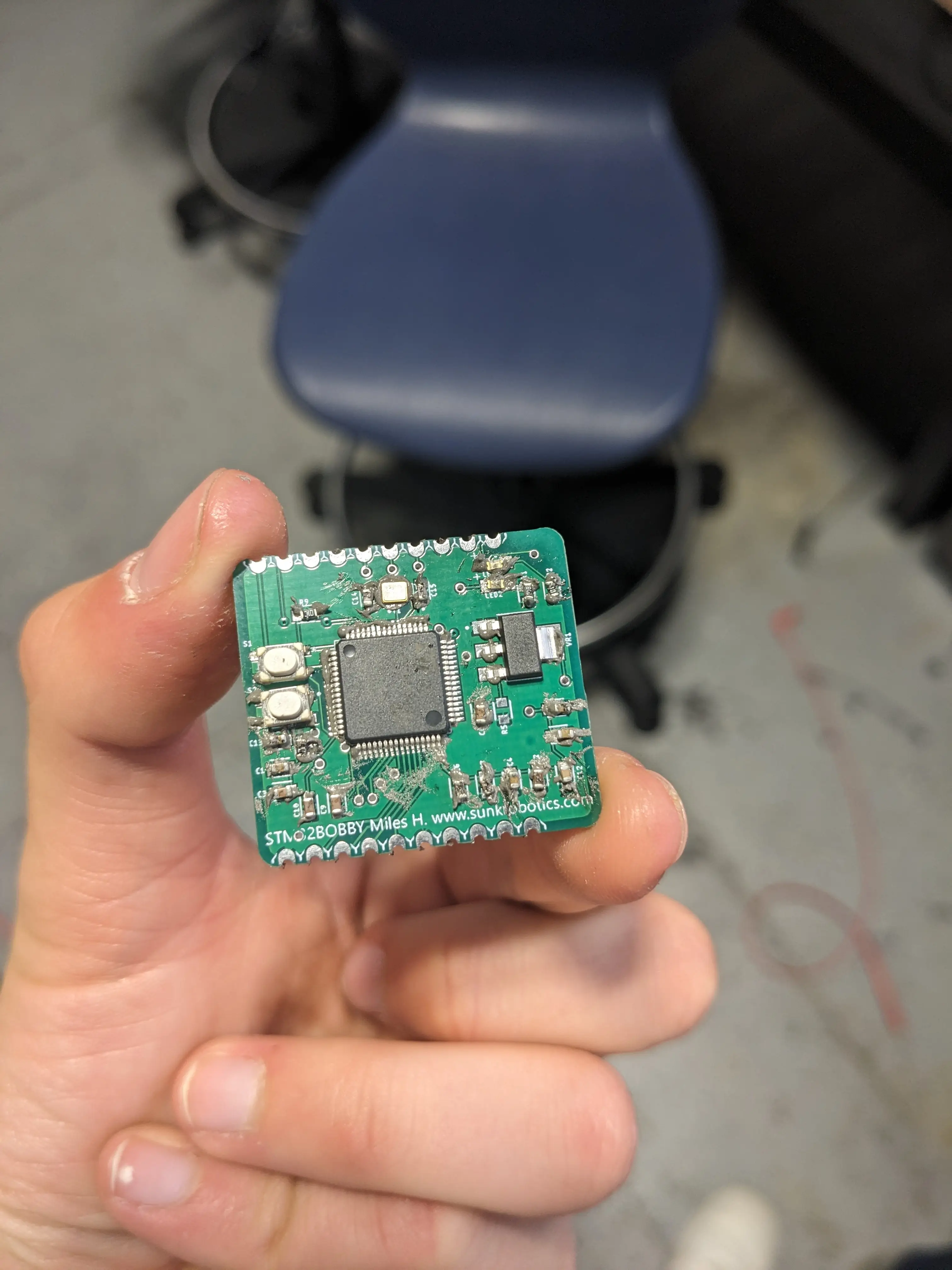
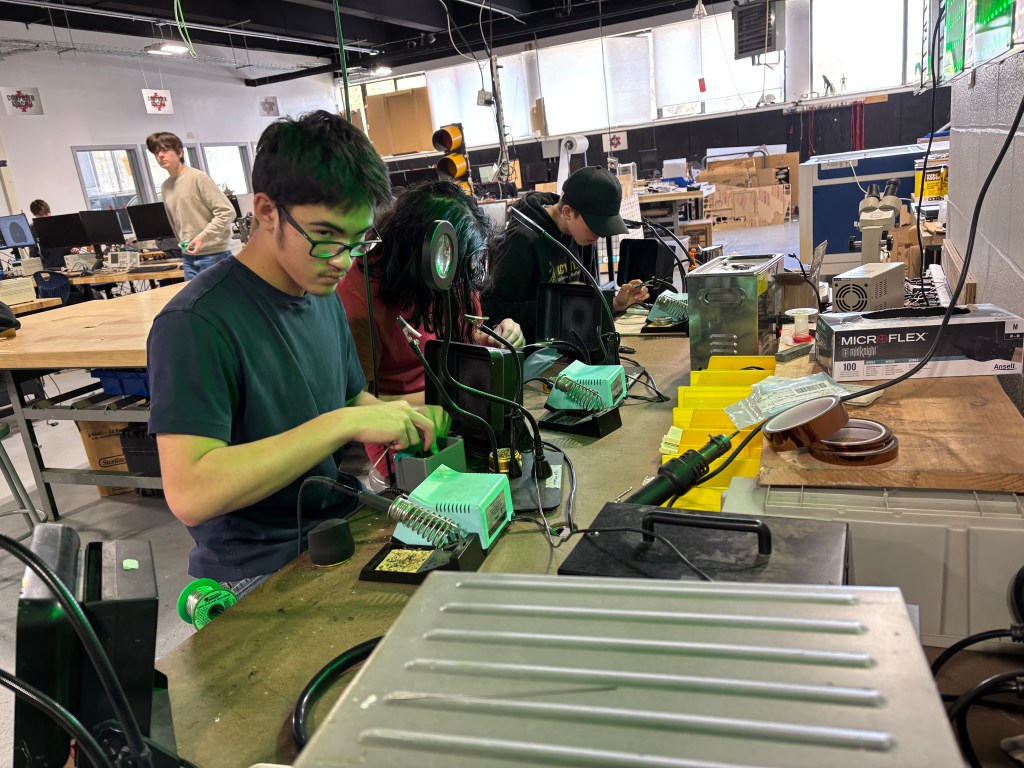
Junior Miles Hilliard ’27 was solving problems with a custom circuit board:
This week was spent mostly with tweezers and a soldering iron trying to place tiny components onto a tiny circuit board.
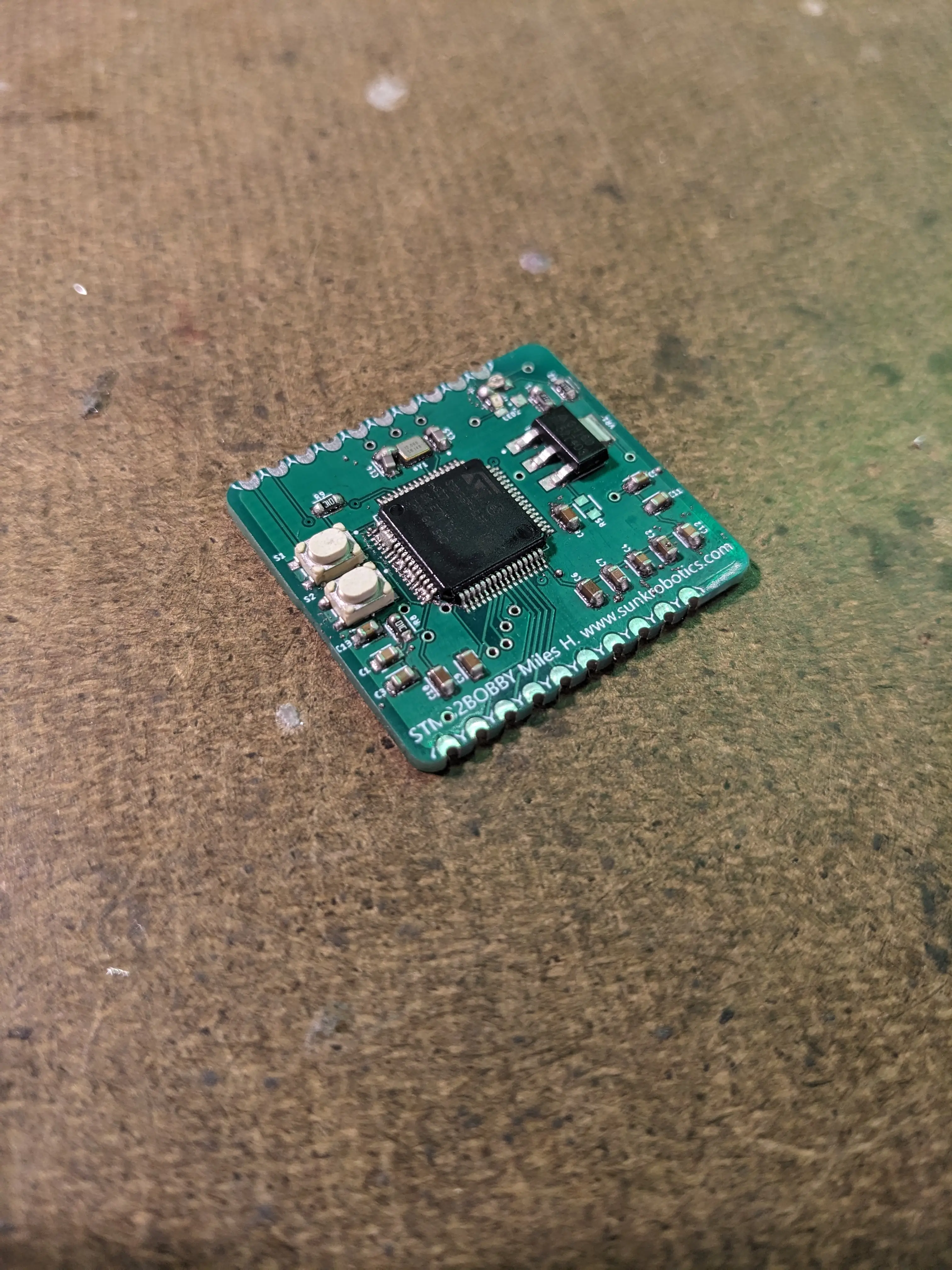
My custom made STM32BOBBY boards finally came back from JLCPCB and so did the components I ordered for it from DigiKey.
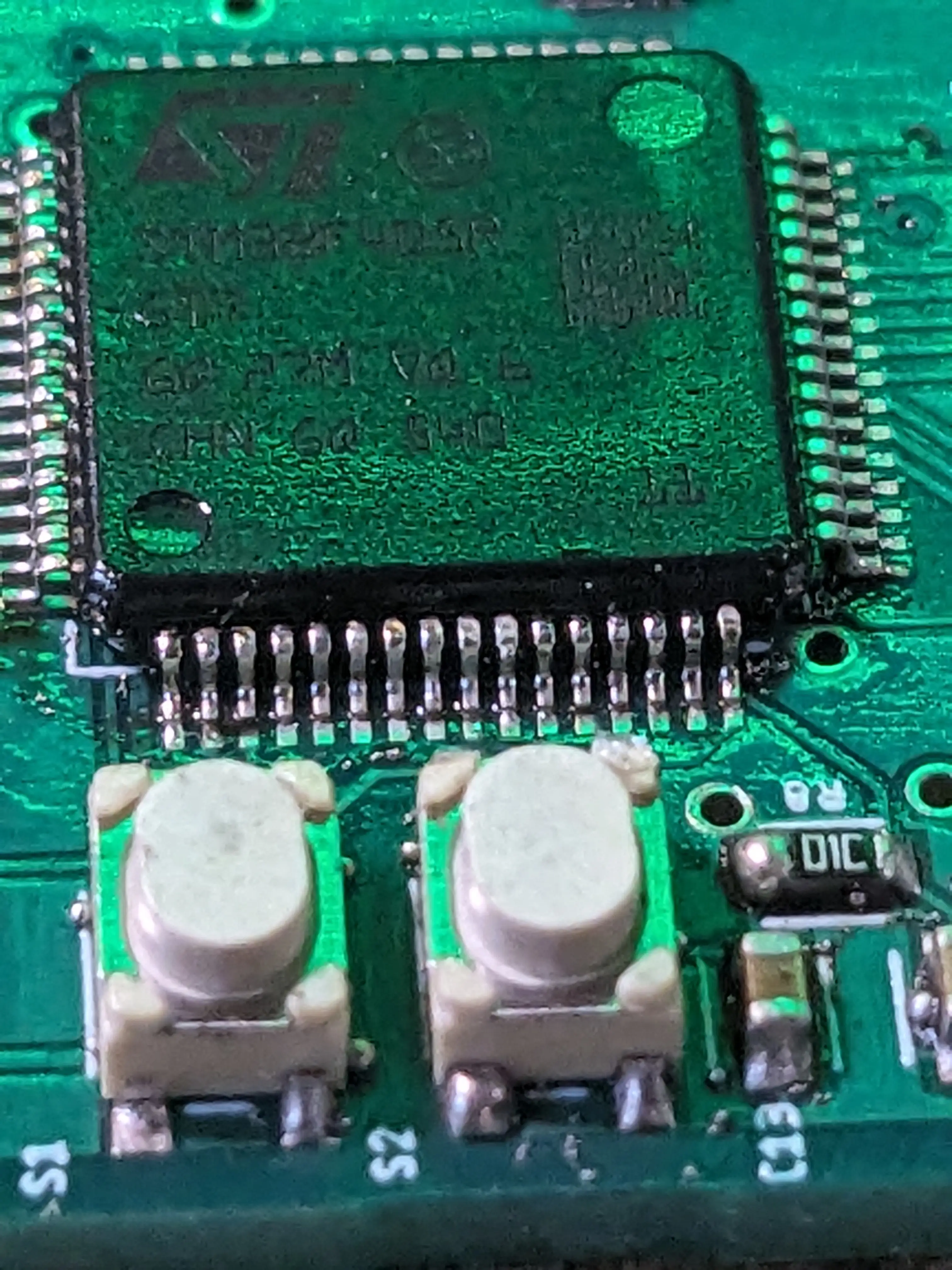
I opened things up and the parts looked way smaller than I expected them to be. I could easily fit ten or fifteen of these dudes on my pinky without a problem.
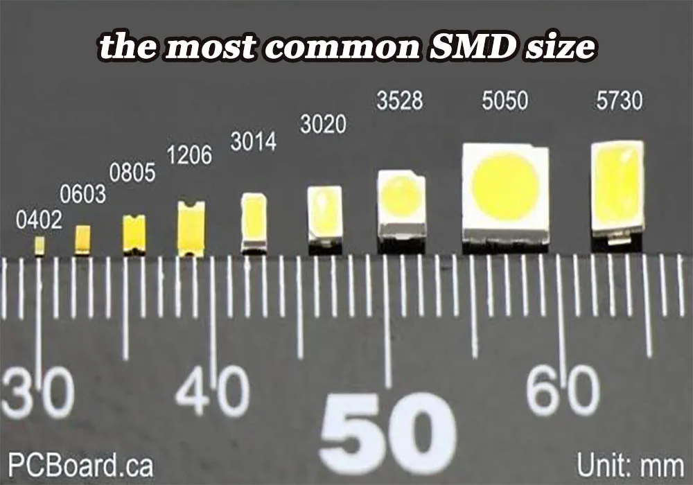
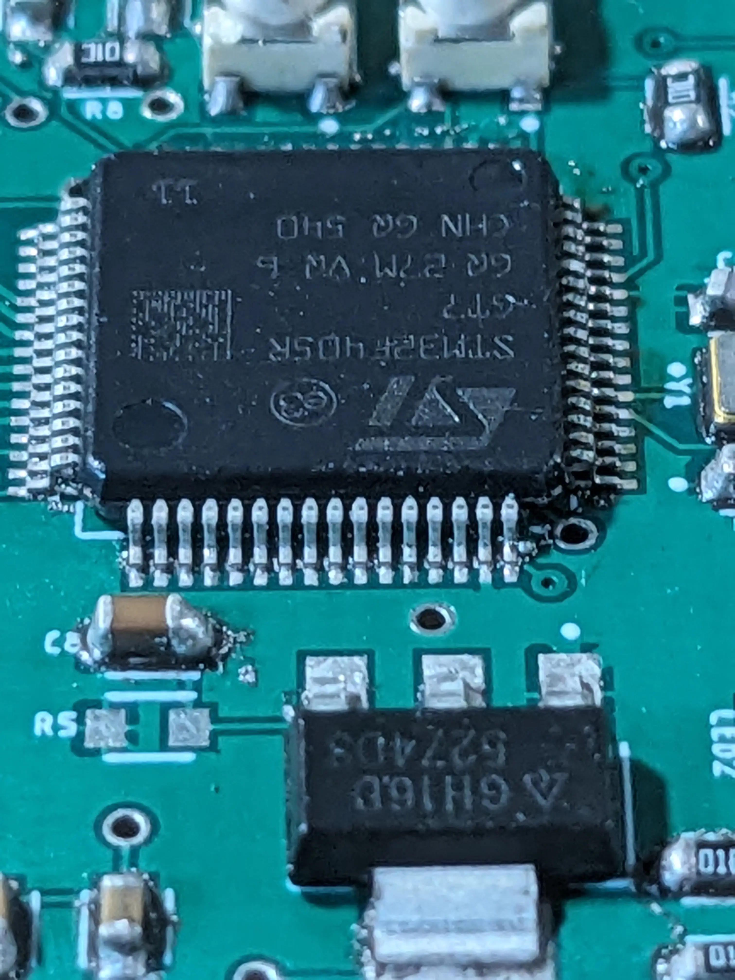
In my case, I designed the board to handle almost exclusively 0603 size components, and as you can see, are basically nonexistent. With the help of some tweezers, a bright light, and a microscope for the STM32 chip, I was able to lay out all the components onto one PCB. The solder paste made the board look extremely messy, but it did help the components stick to the board a bit better before I put the whole thing in the oven for a final cure.
As you can see above, I put way too much solder paste on some of the components. This led to a few electrical problems that were extremely hard to find down the road…
Nonetheless, I baked it in our modified PCB toaster oven and it didn’t look half bad at first glance.
Upon further inspection however, you can see that many components had too much paste left over resulting in large solder balls everywhere. Similarly, some components moved about while in the oven which caused them to strike some interesting poses. Take a look at the capacitor near the crystal oscillator chip… It managed to solder itself to the crystal.
The board did end up needing some rework with solder wick and a soldering iron. I ended up reseatting the crystal too, as I thought there was some problem with the soldering underneath it, however I don’t think this was actually an issue.
After I got it to where I thought it looked pretty good, I have it over to Alachie to take a look at it and try to flash some firmware on it. Immediately I noticed there was a problem. The top and bottom of the pads on the .1″ headers were electrically isolated from each other from top to bottom. This made things a bit harder, as I had to do some tricky soldering to get the header pins soldered to both sides of the board.
Even after figuring this out, we were unable to get any code uploaded to it. The board would not respond no matter how hard we sent encouraging signals to its debugger pins.
Hopefully next week, we will have this sorted out and working flawlessly!
No posts from our Sophomores this week as they made their final push to finish the LED Light Box Project. They will be presenting their boxes to the upperclassmen for grading.
Our Freshmen finished their CAD Star Wars Droid Project. We are in the process of 3D printing their final designs. They will continue with coding and circuitry this week.
All for now.

You must be logged in to post a comment.