
We ended this week with a field trip to Tulip Infrastructures in Assembly Row. The tech company invited the shop to educate students about what they do, and what a career in engineering could look like. Students listened to workers from Tulip discuss their pathways towards a career, as well as understanding more about the products and services offered by Tulip. Thank you Tulip for bringing us into your office and helping to educate tomorrow’s engineers.
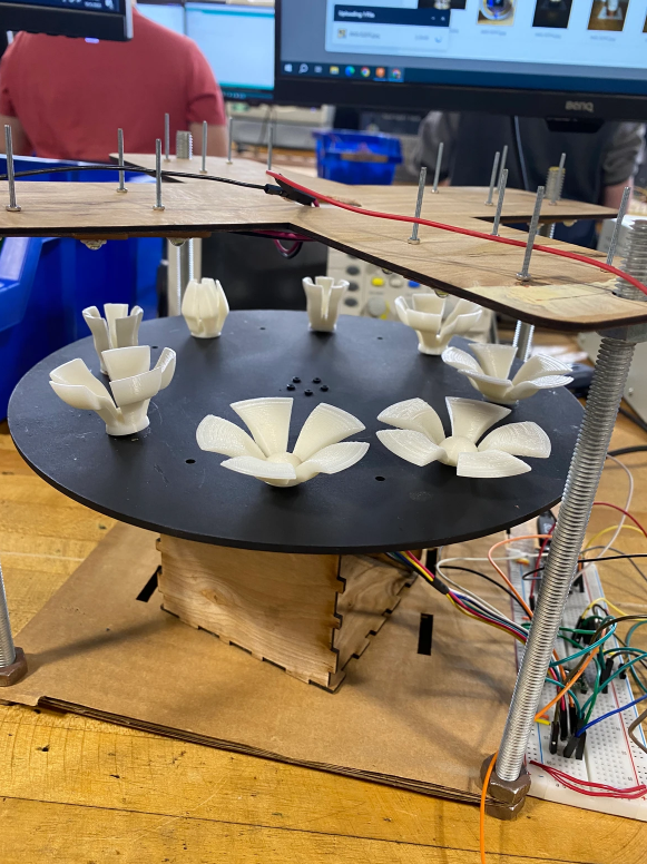
This week Junior Tanzerul Azam began taking over an older project. The Zoetrope project caught his eye, and he is working on understanding the engineering involved. He wrote on his blog:
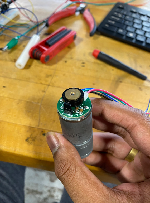
This week I worked more on my 3D zoetrope project. After getting the motor running last week and realizing using the potentiometer for speed control would not be great I decided to let the motor just run at the speed it was and work on trying to configure the lights. In order to do that I needed to figure out the speed of the motor. I did that by hooking up the encoder wheel on the motor to an oscilloscope. The encoder wheel is just a small disc on the back of the motor with magnets inside that can be used to read the position of the motor.
Later in the week I decided to do something about the shaft collar on the motor. The old shaft collar was 3D printed and was a loose fit on the motor causing it to free spin and not reach as fast as it could go. To fix this problem I used the metal shaft collar designed for the motor I am using. I had to completely redesign the disc to completely but that wasn’t an issue. Decided to spray paint the disc matte black to give it a sleeker and cleaner look than the previous disc as well. Soon I will have to rewrite the code and recalibrate the strobe lights on the zoetrope to sync them up again because the speed has now been slightly altered.
See more at his website, click here.
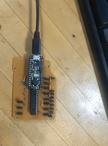
Senior Cormac Lynch has been working on the getting a multiplexer to function properly on his custom circuit board. He writes on his blog:
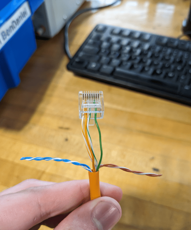
This week I continued to work on my new PCB, first of getting the Multiplexer to work because the wires connecting SDA to A4 and SCL to A5 were switched causing the multiplexer not to work and send an error message when trying to turn it on. After I fixed that, I started to solder the three pin and two pin headers on, one by one. After soldering each pair of three and two pin headers on, I tested them to make sure that the breakbeam sensors would work with the pins. I ran into a few problems during this however, the first of which being that I needed to cross a wire over a three pin header, which wasn’t possible, so instead, I put it on the bottom of the board. This caused the next problem I had, which was that I had to make sure not to burn through the rubber outside of the wire while soldering. This caused me to accidentally not put enough solder on the pins, making them not work. I fixed this by using a multimeter to test continuity and adding more solder to the pins that weren’t connected. In the end I got most of the pins soldered onto the board, and I’ll finish doing it next week.
Learn more at his website, click here.
The Sophomore students continued their coding work this week. They have many more guides to learn in order to be ready to start the LED Light box.

You must be logged in to post a comment.