
One more week until the April break. The upcoming time off will be a nice way to relax before the push to the end of the year. Before that happens, however, here is some of the work happening in the shop right now.
Senior Echo Valdez-Melgar ’26 is working on some gifts for friends and family:
Hello Everyone! Been a minute since my last blog, right? We didn’t have school last Friday, so no blog post last week. This week a bunch of progress was done on the clock and I started a side project that I can work on in the background. The clock is going to take a few more weeks to finish, but its steady progress. Anyways, lets dive into the week!
Starting in on Monday, I worked on(finally) finishing the gears and getting everything in place. I got the Power Reserve(how the clock keeps going after you finished winding it) and the Escapement in. I did change the escapement up from my original model as I could make it more compact so that the other gears had more space in the box and everything wouldn’t be so cramped. As well has changing the balance wheel so it holds M3 nuts as weights instead of the bigger M5. Using M5 would’ve made everything too big. I reworked the Winding gears so that they fit a bit better within the space right next to the front wall, as well as reworking the Winding Key as I didn’t like how it looked.
On Tuesday, I started to convert the Gear Box model into something that I could cut on the laser-cutter. I know I’m going to have to 3d print all of the gears due to them needing to be different depths, and we only have wood that’s 1/4 thick. I used the simple puzzle piece method on most of the box. As the corners of it I’ll have to use some screws at an angle or just wood-glue the corners together. I laser-cutted them and found that the box was kinda small, which is what I wanted. The box is only 3.5×3.5in, but as I was looking that the cardboard prototype, it more looked like the gears wouldn’t fit in there or if they did, it would be a very tight fit. So, I decided to size the box up a bit, making it a 4x4in. Doing that kinda broke the model a bit so I had to spend some time fixing everything. I only got it half fixed by the time school ended as I had something else to do during 7th period.
Wednesday, I figured out a small-ish project to work on in the background but I spent some time working on now. I wanted to make a gift for a Teacher who wrote one of my Letters of Recommendation, and I decide on making them a pencil holder for their desk but based it off of a video game character they like. I found a model of a little robot companion that the character has and decide to make that the pencil holder. It was basically just a big sphere, so it wasn’t that difficult to hollow out and model in supports for it plus a platform for it to sit on. The problems started when I went to print out the pencil holder. My first attempt at printing, it failed and when I tried my second attempted but thinning the sphere, it also failed. I asked Mr.L to look at it and he told me that it just needed more supports on it. I just switched to resin printing it as a line has sorta formed for the 3d printer as my sphere takes a while. I finished fixing the gear box by Thursday, but I had to continue to work on the gift as the laser-cutter was being used all day. Taking the supports off of a resin print always takes a minute, so that took a few moments of my time. I spend the rest of Thursday just transferring and labeling all of the other gears into a file on my Google drive. I plan on starting to print out all of the gears on Friday, I just need to decide if I’m going to 3d or resin print them. I’ll also be able to finish the gift by Friday’s end too.
See more of Echo’s work at this link.
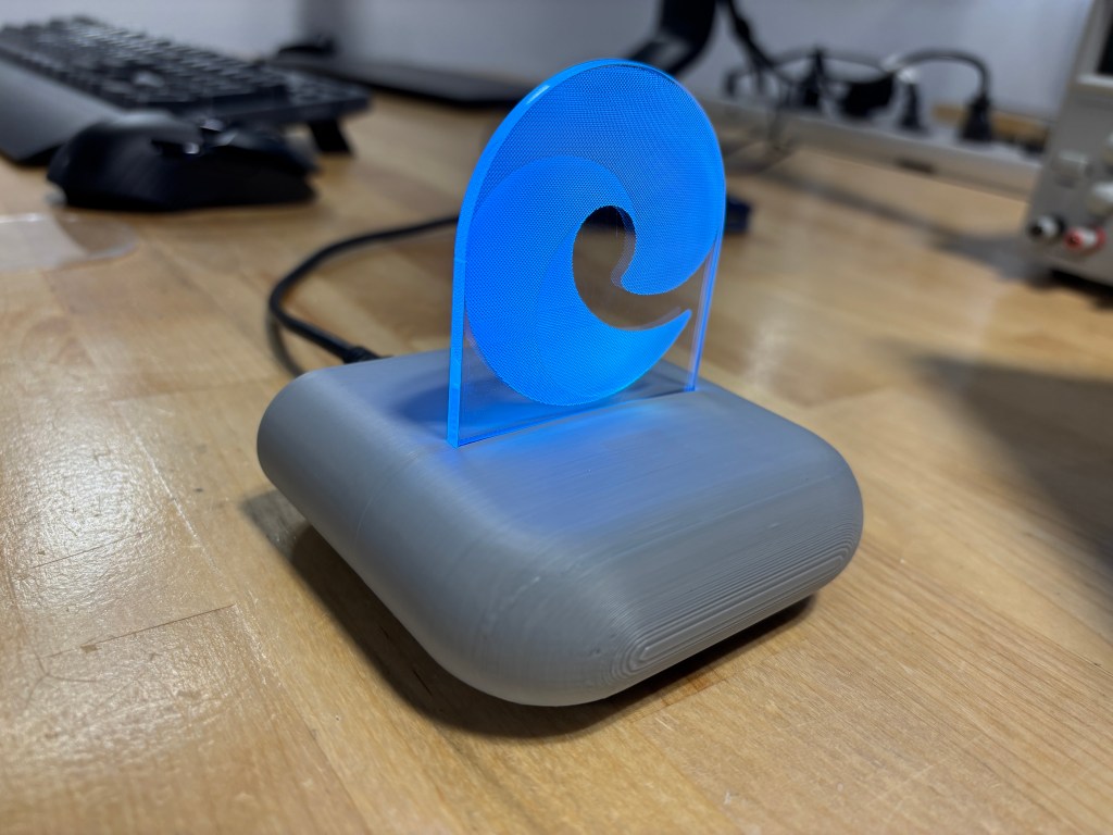
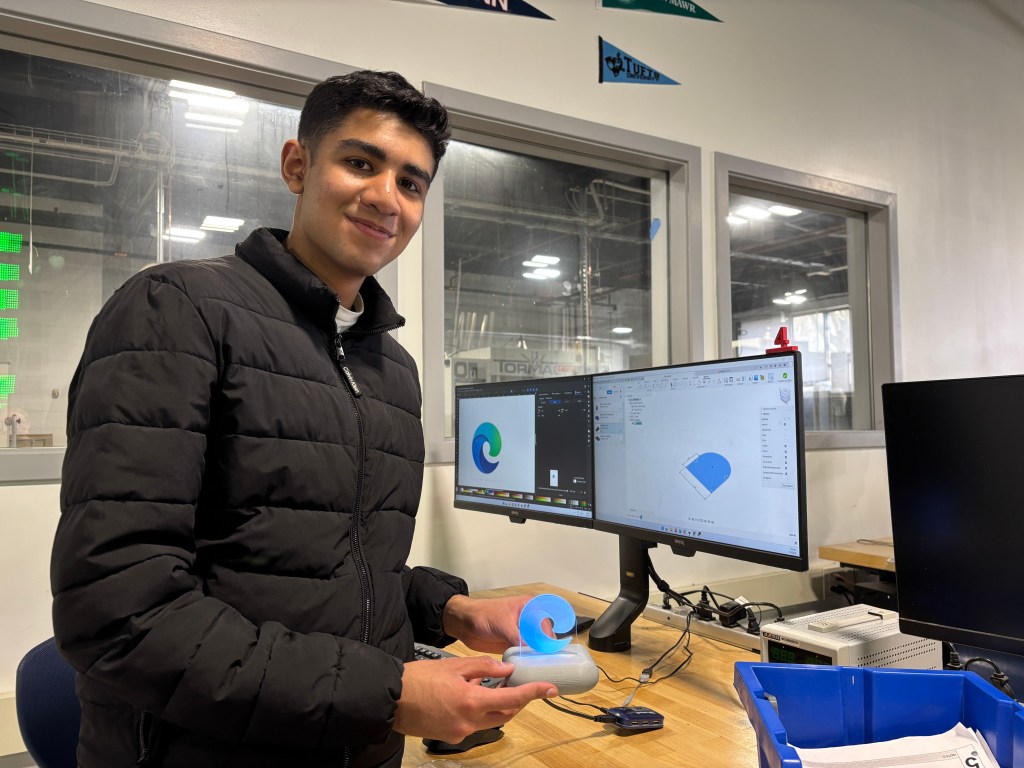
Junior Sydney Hamel ’27 began designing a new project for a candy sorter:
Over the past two weeks lots has been going on. School was cancelled on Friday, so we did not make blog posts, but I’ll cover everything here. I delivered all of the speakers to their respective APs, and everyone loves them and are very grateful. They think it was a wonderful way to repurposed the vape batteries. Whenever I have a little extra time I’ve been working on a speaker for myself, which is almost complete, but it is not a priority. The main focus is now an M&M/Skittle sorter, which I’m working on with Quinn.

Before we started the Candy Sorter, Quinn and looked at an old sewing machine of mine, which did not smell good when in use. We figured it would be the motor, so we opened it up, got the motor out, and opened the motor. Inside there were two small metal pieces that were getting eroded, so I ordered a new motor, which has not yet come in. I’m hoping this will fix the problem because the machine is pretty nice.


Once we figured that out, we moved onto the Candy Sorter. We started by doing a little bit of research; figuring out how other people have made them. With this information, we determined that a vertical cylindrical design would be somewhat fast at sorting while not getting super complex. I sketched an initial idea for how the machine would work, and I have made a few others since. Quinn and I then started designing on CAD. We measured the size of each candy, and made Global Parameters that we can use across all of our part files. This was our first time making Global Parameters, and it is super useful.
I designed the top tube. We’re hoping to just cut a piece off one that we have and then 3D print an insert that creates a slot at the bottom and angles the bottom towards the slot, so that all of the candy pieces will go in it to get sorted. While I was working on this piece Quinn designed a disk that will go beneath. There will be a thicker one that rotates, and just has one hole into which a single piece of candy will fall. There is a disk underneath the rotating one as well that is stationary. When the single holes on each disk line up, the piece of candy falls through. The middle disk continues rotating, getting another piece of candy and repeating. This system allows us to get one piece of candy out of the supply in the tube. We laser cut all of these parts, and got it working with the motor, which was very exciting.

This piece of candy will then drop into a small box. Inside the box there are two ramps, and at the bottom of the second is the color sensor. While the candy is sitting at the bottom, the color will be sensed. The plan is that there will be two more disks beneath, using a similar method as above. The top one will be rotating, and when the single holes comes around it will get the piece of candy that has been sensed. The disk below it will turn its singular hole above the section that color goes in. When those two holes line up, the candy will fall into the correct section.

I designed most of the color sensing box on Thursday, designing it to be laser cut since that is way faster than 3D printing. At the same time Quinn made a 3D design of the motor, though we might change what motor we’re using: this part is not yet finalized. Despite this, we do know that the motor will be in the middle of the top tube, spinning the whole axis from there. Quinn and I look forward to where this project takes us, and I know that I have already learned a lot.
See more of Sydney’s work at this link.
Sophomore Dom Lyons was working on his LED Lightbox:
This week was a week of prepping to create the components to my lightbox. I first began with my light strip. The first thing I did was the cut the strip and I used an exacto-knife to scrape off the copper cover to reveal the copper beneath it. I then cut off three strips of wire; a red for power, a blue for DIN, and a black for ground. I quickly began to solder and was quite easy. I then put heat shrink over the exposed wire so that it was and looked more secure. In the process of heat shrinking, the heat shrink shrunk too low so then I tried to get it off with flush cutters. This was not a good idea because the heat shrink was stuck to the wire and eventually ripped the solder off, making the light strip unusable. Finally, I had to repeat the process after a couple of tries and was successful.
These are pictures of the light strip up close. There are also picture of the light strip lighting up with my breadboard. There are two pictures that show the light strip lighting up, one of which is a darker shade of blue when the light sensor goes off. It is quite hard to tell the change of blue in the images.
I’m going to transfer the components on my breadboard over to my PCB for the lightbox.
See more of Dom’s work at this link.
The Freshmen were working on their Droid project during the week. They will hopefully begin 3D printing them after the April break.
All for now.

You must be logged in to post a comment.