
A solid week of work from our students. So many interesting projects happening all the time, it’s hard to keep up with them all. Below are some highlights from the week.
Senior Matt Stricker ’26 continues work on his walking robot:
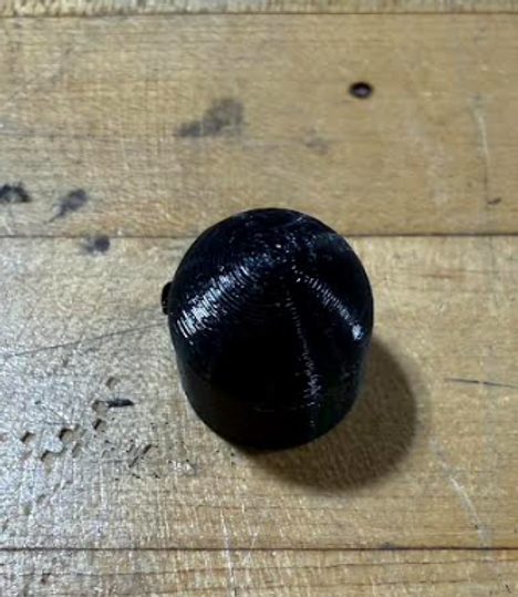
At the start of this week, I was finishing designing the cover part for the hexapod and scaling up to a size that looked best, but also fit the space where it needed to go. I designed it after a similar robot from a game I like, so I tried to make it look pretty accurate to the real thing. This led me to scale it to about 1.3 times the original size since it looked pretty weird when it was so small before.
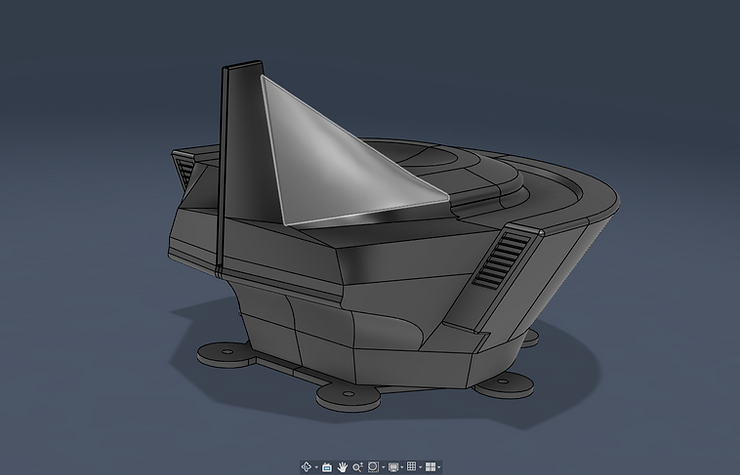
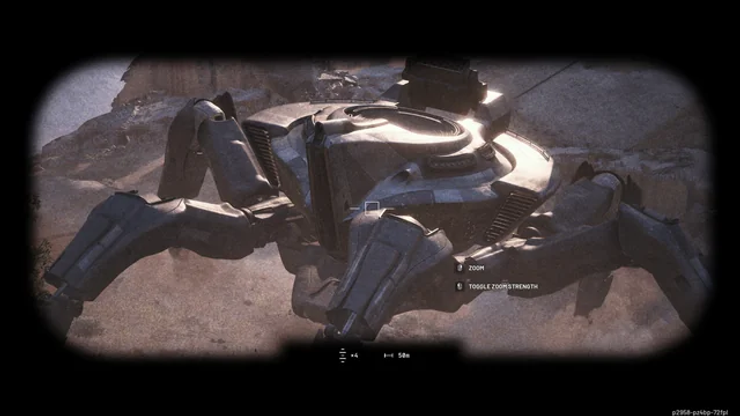
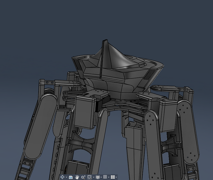
With the legs in place, the cover looks pretty good, and I also hollowed it out so that it would be light as well as being a place for the electronics to go, so you wouldn’t see them very much except for the bottom part I had to spend some time raising in it up though, since it was intersecing with the motors closest to it, but that got fixed eventually. Modeling something after something else with such a complex shape turns out to be pretty hard, but I think I did a pretty good job, and I also left a spot for a strip of red acrylic to simulate the light on it. I hope to print it out soon.
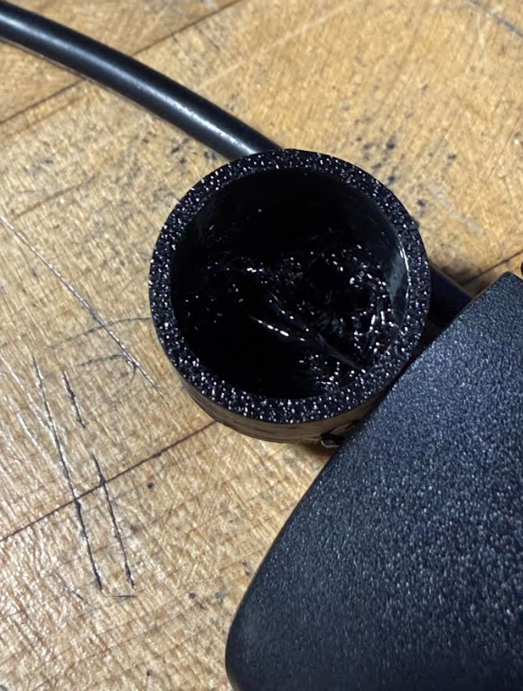
Also this week, I realized that the printer was set up for the 85a tpu, which I wanted to use to print out the endcaps for the feet of the robot that would grip the ground, but my shop teAcher suggested trying the less flexible tpu first. I tried it, and it messed up the inside, so I will need to simplify the part to make it easier to print.
Since I used the other TPU, the grip was almost non-existent, and the feet did not work very well with them attached, so I will definitley ty to use the other TPU next time, but it takes longer to set up, and there have apparently been some issues with printing parts with it, so I will look for other options. My shop teacher also suggested making a mold and using silicone instead, which might be a good idea.
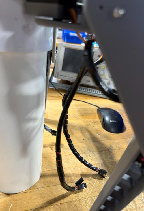
Towards the end of the week, I also finished up the wires on the robot, since I had been putting them off while I worked on other things. I managed to wrap the remaining wires and crimp them, but it was just a lot of tedious work.
See more of Matt’s work at this link.
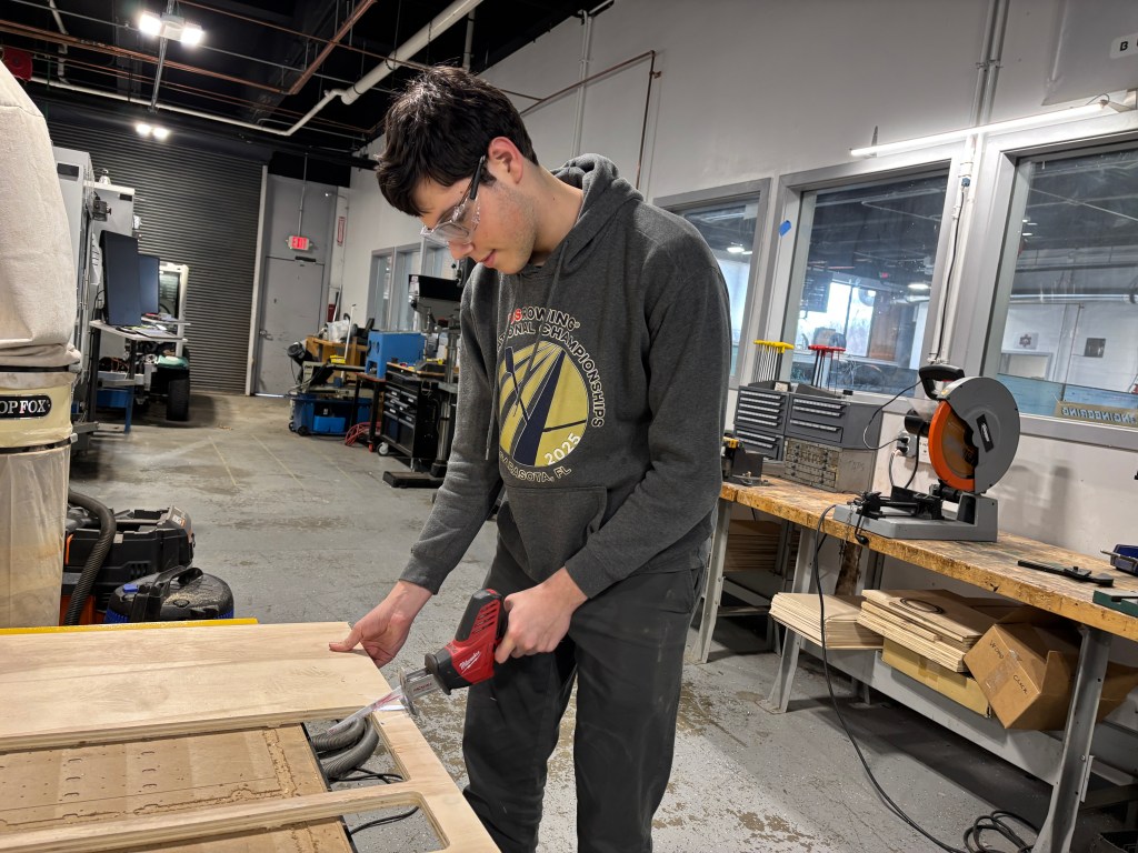
Junior Lila Graham ’27 is nearing completion of a custom storage shelf project:
↳
Mar 26
I didn’t post last week, but I have made a lot of progress on my shelf in the past two. I cut out the rest of the pieces for the shell/walls, assembled them all, and set up my shelf and drawer pieces to cut.
The first thing I did was cut out my side walls, so that I could glue all the smaller inside pieces together. The piece would not fit on the pieces of wood that we have, so I had to split the sketch in Fusion and transfer that over to Inkscape. It ended up looking like this, and the smaller pieces I was able to cut on one board, but I needed separate ones for the larger pieces.

I cut these all out, sanded them off, and glued the separate pieces into one, holding them together with clamps. I just used white glue, and it seems to be working well and staying supported. I repeated the process, gluing all the pieces from the previous week to the surface of each outside piece, and I had my side walls. I did have to redo a few of them that didn’t stick the first time or that I oriented wrong, but otherwise smooth sailing. While I waited for the glue to dry, I helped my classmate Quinn a bit with the painting of a quark puzzle project.

Next, I glued the walls to the top and bottom of the shell, creating a hollow shelf. I used some larger clamps to hold these together while they glued.

Finally, I glued the back of the shell to all the other sides. This I held down with giant jugs of stuff we had lying around, as the clamps were too short.

For some reason, the shelf I had cut out was too short to fit into the shell, despite it being the same size as the Fusion design says it should be. I adjusted the sizing to fit the shell and cut it in cardboard just to make sure the new one works, which it does. I can cut all the shelves in wood now.


The last thing I need to do is cut out the pieces for the drawers themselves, so I started setting up those files in Inkscape. I’m adding a bit of an extra step to the files because I want to be able to fit as many pieces as possible on one piece of wood so that I can stop cluttering the bin of laser-cut wood with half-used pieces and filling up the space.

Also whilst waiting for glue to dry, I began researching a project that Mr. Christy brought up, namely creating jewelry out of used/old circuit boards. These are some ideas that I liked in my search among many others:


I am so happy to finally have a working shelf, and I feel like progress is being made at last. The shell fits perfectly in my closet, and I am so excited about how it’s turning out!

See more of Lila’s work at this link.
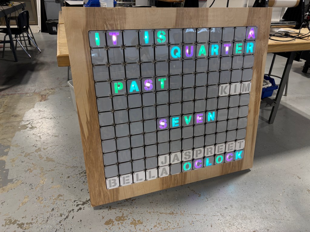
And Sophomore Adam Dangi ’28 believes he is working on the final phase of the LED Lightbox Project:
This week, I continued work on my light box project.
Additional Notes: From now on, whoever helps me with work or otherwise will have their website listed below(engineering is better as a team effort), think of it as a shout-out.
Monday: I began Monday by making my goal sheet(always important). Then I begin work on adjusting the size of the entrance for the acrylic on my lightbox. The week before, I had one of my fellow classmates, Alachie, laser cut an acrylic for my light box. The area where the acrylic slides into was originally measured as 1 inch; I resized it to be 2 inches. That concludes Monday.


Tuesday: Today I had to deal with several issues on my light box, well, in hindsight they are fewer issues and more like things I need to have before I even THINK about 3d printing. The biggest one being the fact that I needed to put a plug spot area for my USB Breakout Header. Before, I had just extruded a rectangular cut through the side of the box; however, after being informed that I should use a plug, I projected the Plug onto the side of the box and extruded that shape’s cut into the side. After I use the move tool to move the plug into place, resulting in the images below.


Wednesday: Today, I had Mr. Lewkowitz check my box for anything needed. He pointed out several things, of which I will now talk about. First off, the original threaded holes I had didn’t actually reach all four corners, so I quickly changed it by using the rectangular pattern tool. Second, the PCB was just kinda hanging around on the ground. Not good, as that could be an issue, so I have four cylinders have it up a bit in the air. That concludes Wednesday.


Thursday: Today was playing the waiting game. Mr. Lewkowitz told me that to test if the screw would work or not, he was to 3d print a cylinder, like the ones that are holding up the PCB inside the box. So, I made a new Hybrid File, copied the design of one of the cylinders, and then exported it to my drive as a .DXF file. But unfortunately, I had to wait for 3 other people’s turns before I could use the 3d Printer. And while I could use the milling machine while I waited, I wasn’t taking any risks with that machine again, and so I spent the 15 minutes left waiting and writing what you are reading right now.
Friday: Today, I will 3d print a cylinder with a hole(threaded) to test out the M2.5 screws. Once I do this, I will begin either 3d printing the actual box, or finally getting around to milling a PCB of the current light box components themselves.
See more of Adam’s work at this link.
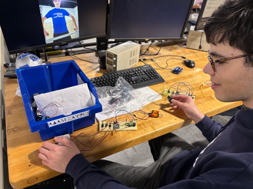
The Freshmen worked on CAD this week, with a Star Wars Droid Project. Students designed, by hand drawing, a Star Wars Droid, and then transferred that image to CAD. The designs will be modeled in CAD and 3D printed. Next week its back to circuity and coding with Mr. Christy.
All for now!

You must be logged in to post a comment.