Looks like we may be over the hump with winter as temperatures are looking to rise as we enter the second week of March. A lot of progress is happening in the shop, so let’s get right to what students have been working on.
Senior Reid Pacini is finalizing his CD stand:
This week I continued working on the CD organizer project and started wrapping things up. I started the week by finishing some new designs that I started at the end of last week. Unfortunately there were some issues importing those as DXFs into Inkscape which I think had something to do with the splines after looking it up.
After running into these issues I decided to go back to using one of my original designs that was square and did not use the splines. this design imported into Fusion fine and I faced no problems.
I also was able to bring some of my CD cases into school on Thursday to measure them and make sure the measurements I already had were correct. Once I measured them I realized that both the width and the length of the slots on the holder were a little too small so i fixed those before I exported the pieces to Inkscape to get ready to cut them.
Junior Alex Bress continues work on the octave switcher:
This week was yet again a short week, since Tuesday was a professional development day. Most of my week was spent troubleshooting the new octave switcher and getting it to function properly, since there were numerous obstacles in the way.
The first of these obstacles was the power supply. Normally, with only 4 microcontrollers, the circuit is able to run perfectly fine with only one USB-Micro cable and the rest daisy-chained off of it. However, the 5th Trinket acts as the straw that broke the camel’s back, and the entire circuit breaks down. This is especially bad for the communication system, which relies heavily on timers, which need a stable power supply to function. What I ended up doing was powering the master through a separate cable, which has the added benefit of being able to upload code without needing to switch manually.
The next problem was with the timing issues caused by pulseIn(). While I cannot directly shorten how long it takes, I was able to shorten the code around it, which has a similar effect. The first thing I did was change the variable from int to byte. since this uses half as many bits, it can read and write much faster. I also removed as much math as possible, instead offloading it onto the master Trinket. Finally, I changed the variable to be volatile, which runs on RAM instead of storage, so it can run much faster than before.
Finally, and most embarrassing, I had to fix a spelling issue. On my final test run, I misspelled INPUT as IMPUT. Somehow, this didn’t register as an error, and I didn’t notice until the very end of the day which really tripped me up. Next week, I hope to get the code running in its entirety. I may also add some more efficiency, such as switching the pow() function to bitshifts, although I will most likely stick to the basics.
Sophomore Michael Tirella has nearly completed his circuit board in CAD for the LED Lightbox Project:
This week was once again spent on working towards completing the Light Box project. More specifically, I worked on the schematic of my electronics, and the 2D PCB.
This is the completed schematic. I spent a majority of the time working on this, and making sure all worked well. I struggled with some parts, such as beginning it, but once I had gotten some placed, everything fell into it’s place. A notable part is the section connected to pin 2 and 3. This was a late addition we were told to add by Mr. Christy. Though it was late, it was very welcome. It’s purpose is so that we can recode the Light Box without the necessary step of removing the AT mega. That is no longer, as with the addition of this new area, we can code while it is attached to the board. This is pleasant for me since I was planning on changing the colors of my Neo pixel stick.
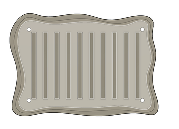
This image is the rough idea of how it will look on the board. I had to go through a couple iterations as I used the wrong pads, but in the end it all worked out.
What you see here is the decided paths by the computer, and is the one I chose was best. I believe I could’ve been more space-efficient, but I think for a second time this is very good. I like how it looks and are excited to get to the step of soldering in the future.
This is what my board looks like imagined in 3D. this will help me in the process of making the actual box around this. I plan to add wires from the neo pixel to the headers to make it easier to create. This will also allow me to place the board further away from the top, more likely near the back bottom with a plug in mind.
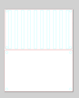
Lastly, this is what the bottom of the board looks like. A better visualization of how I will solder my components onto the board. When looking, it seems it will be easy to solder as not many pins are near each other, besides pins of the same component. that is the only worry when soldering.


You must be logged in to post a comment.