
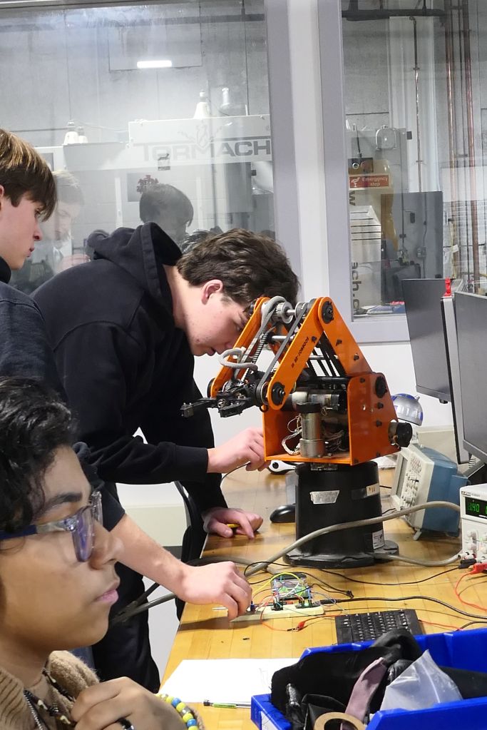
This week we welcomed our new freshmen into the shop. We currently have 14 new Engineering & Robotics students and we could not be more happy with this new crew. We are excited to get them started and learning all the shop has to offer!
Our upperclassmen continued work on their projects. Senior Echo Valdez-Melgar worked on a variety of projects this week:
Hello Y’all! This week was spent working on the Lasy Susan for my sister, it was originally for her birthday but it’s only a month late. No time pasted at all. I’ve also been brainstorming what to do after this project is done, which I haven’t made much ground on. Anyways, let’s jump into this week in The Shop.
Starting off Monday, I finished the Poster Project I’ve working on for the last few weeks. I cleaned up the wiring and did some last minute checks to make sure that nothing magically broke over the weekend. As I was doing these last minute checks, the wires to the battery pack deiced to break, fantastic. Lucky it was a simple fix, just replace the wires with the wires we have in the shop. I was able to take it home that night, I’m still on the hunt for some thumbtacks I have in my house, so I wasn’t to hang it up yet soon thought. I started finishing up the Lasy Susan model in CAD but I wasn’t able to finish it up before the bell rang.
Coming back Tuesday, I finally finished up the model. I wanted to do a size test in cardboard just to make sure it would fit on my sister’s drawer. As I was cutting it out, I quickly realized that it was way too big. Scaling it down in CAD didn’t take long, but I did do double checks on basically all of the measurements to make sure that it was the right size this time. I’ve also decided to cut some of the makeup holders in half, as the whole thing was a bit too tall. The 3d printers had a long line of people waiting to use it, so I used the resin printers to print out most of the parts. The actually base of the Lasy Susan I cut out of 1/4 wood, as it would basically hold everything and I wanted it to be strong.
I didn’t cut out the holes for the stands on the wood as I thought I could just drill out the holes but as I was doing just that, the drill kept breaking and splitting the wood. I decided to just re-cut the wood after adding the modeled holes in Inkscape. The pieces was finally done printing by the start of Thursday, I got them washed and cured in their respective machines. It took a while to remove the supports and sand the pieces down, but they turned out great! I have to re-degisn/add some things to the spinning part of the Lasy Susan as I forget that things don’t naturally spin on their own. I’m planning on getting that done on Friday as well as washing and curling the holder pieces I set to print out at the end of Thursday.
You can learn more about Echo’s work at this link.
Junior Tim Hunt continued work on the ROV:
I spent this week doing some touch ups on the ROV, contacting people to talk before purchasing materials and manufacturing. I also contacted the syntactic foam supplier about required PPE. I also asked about mold release, vacuum chambers, and cast procedures.
This week I also helped a couple people with their projects. Notably I helped Andrew with his key caps and his case. The key caps I suggested a different print orientation so that the stem would work properly. I also helped to remove support from the failed key cap print.
I then worked with Adam S to try and salvage the failed key caps. Our plan was to make an aluminum replica of the post the key caps go on, then heat the replica and melt it into the keys. This did not work very well because the melting temp of the tough 2000 resin was much higher than we could reasonably achieve. Instead The keys just burnt and rubberized.
On the ROV I added the rear adjustable buoyancy material. This is a cylinder with a mounting hole and clearance for other hardware. To adjust the buoyancy the length of it can be machined down.
I also helped Andrew with the design of the case for his keyboard. I walked him through the mounting holes and adjustable PCB hold down parts.
Read more about Tim’s work at this link.
In addition to our Juniors and Seniors, our Sophomore have begun writing blog posts to showcase their work in the shop. We will continue to add their posts to our weekly blog.
This week, Ibrahim Ahmad was working on his LED Lightbox Project:
Introduction
This week was rather unproductive due to unforeseen circumstances with my PCB. Despite successfully soldering all components, I encountered multiple issues that led me down a troubleshooting rabbit hole. In this post, I’ll walk you through the problems I faced and how I eventually solved them.
Soldering the PCB
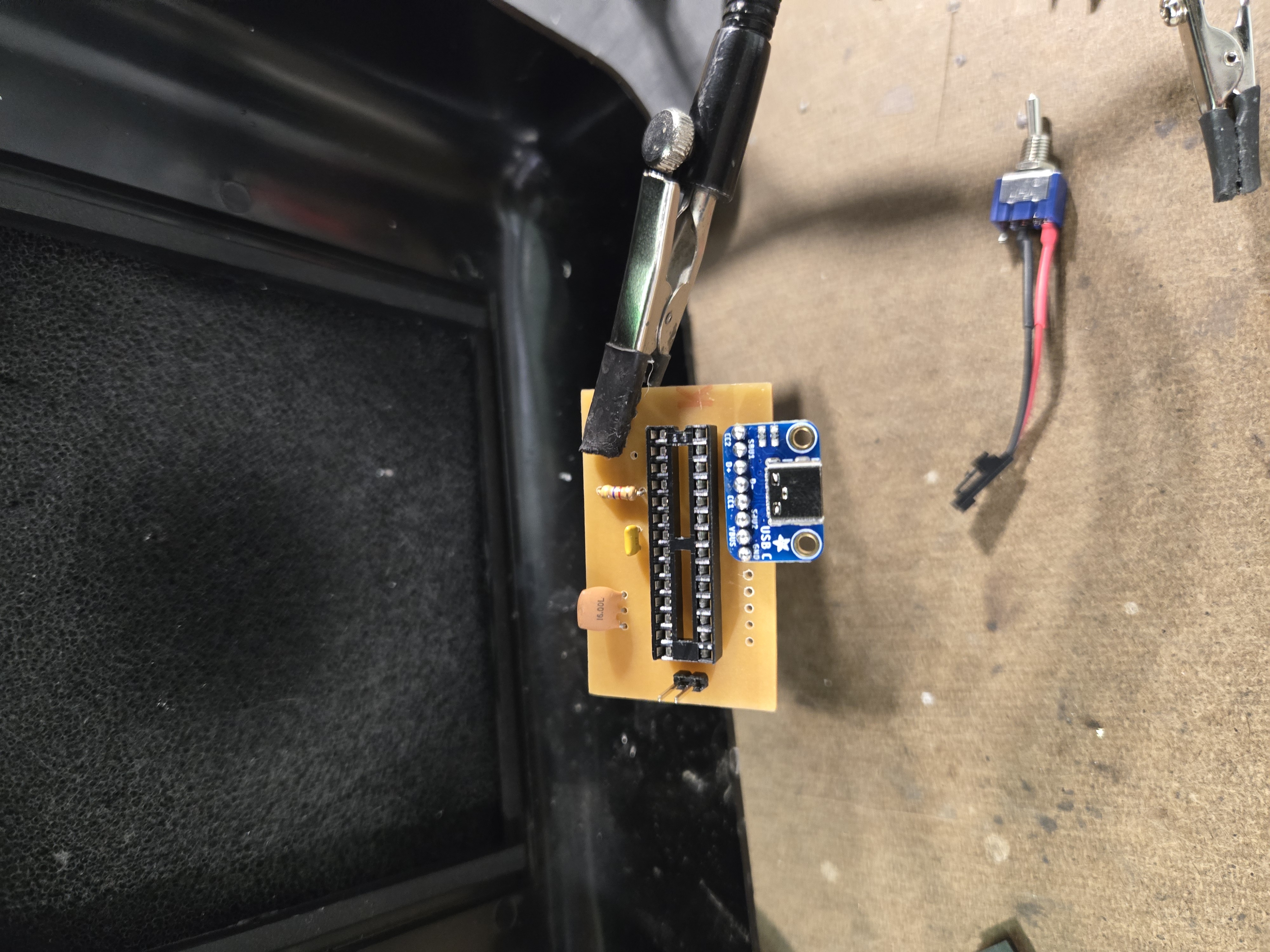
The first thing I did this week was solder the components onto the PCB I milled last week. This was the easiest part of the process and the most rewarding.
Soldering components onto the freshly milled PCB
All components assembled on the PCB
Troubleshooting:
After soldering everything together, I powered on the PCB expecting to see the LED light up. Unfortunately, nothing happened. I spent hours trying to figure out what went wrong.
First, I used my multimeter to check continuity and verify that 5V was being supplied to the LED. The power was there. I systematically checked each component, and I realized that all my components were being supplied power except the actual microcontroller. There was the problem!
Using some short jumper wires, I created temporary traces to make sure everything else was working. My LED still wouldn’t light up. So I tested all my components separately by adding them to a working board. Both the microcontroller and LED worked perfectly in isolation. This meant my PCB had a design flaw, but I couldn’t pinpoint where.
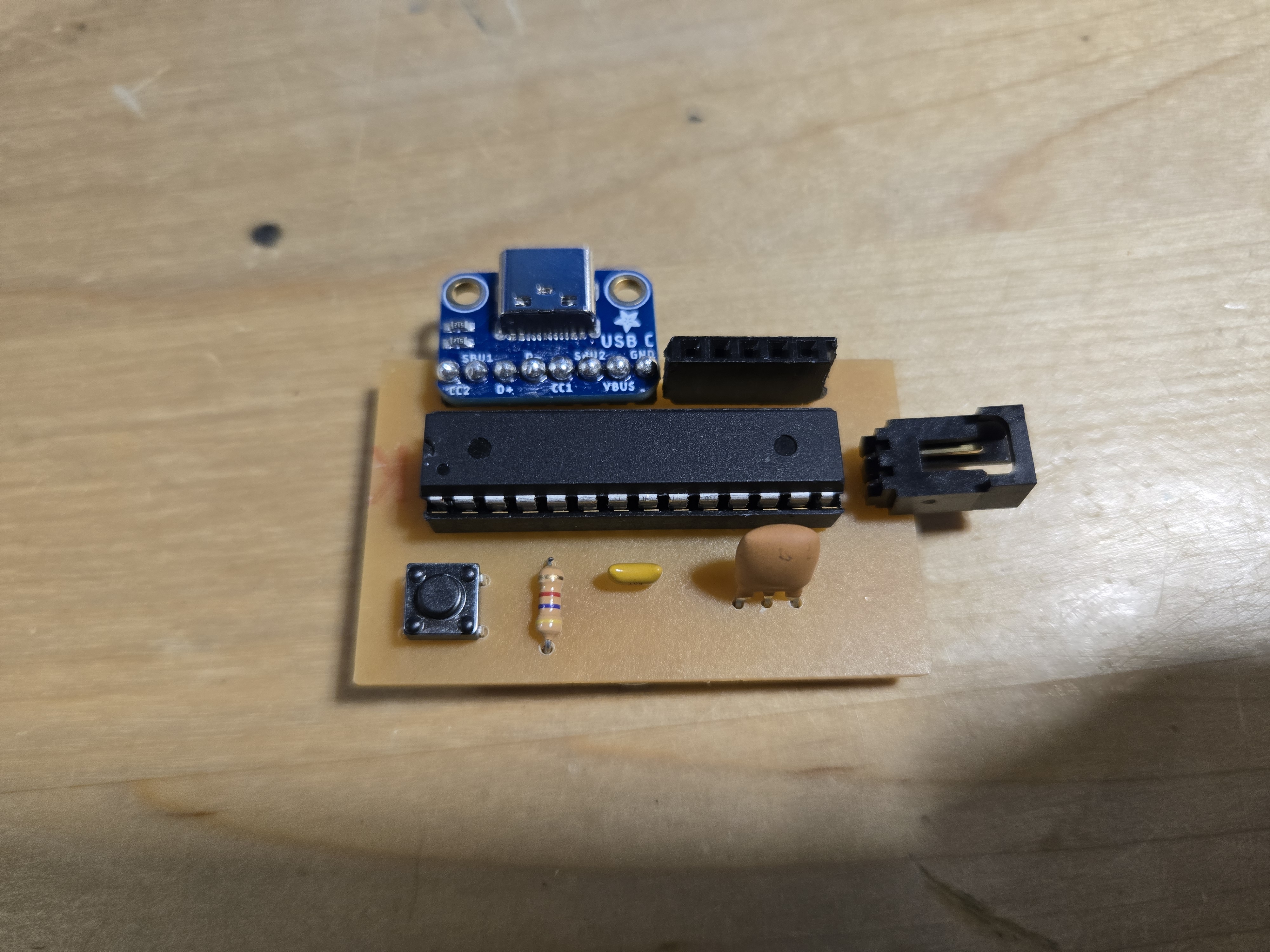
The completed PCB ready for testing
The Accidental Discovery
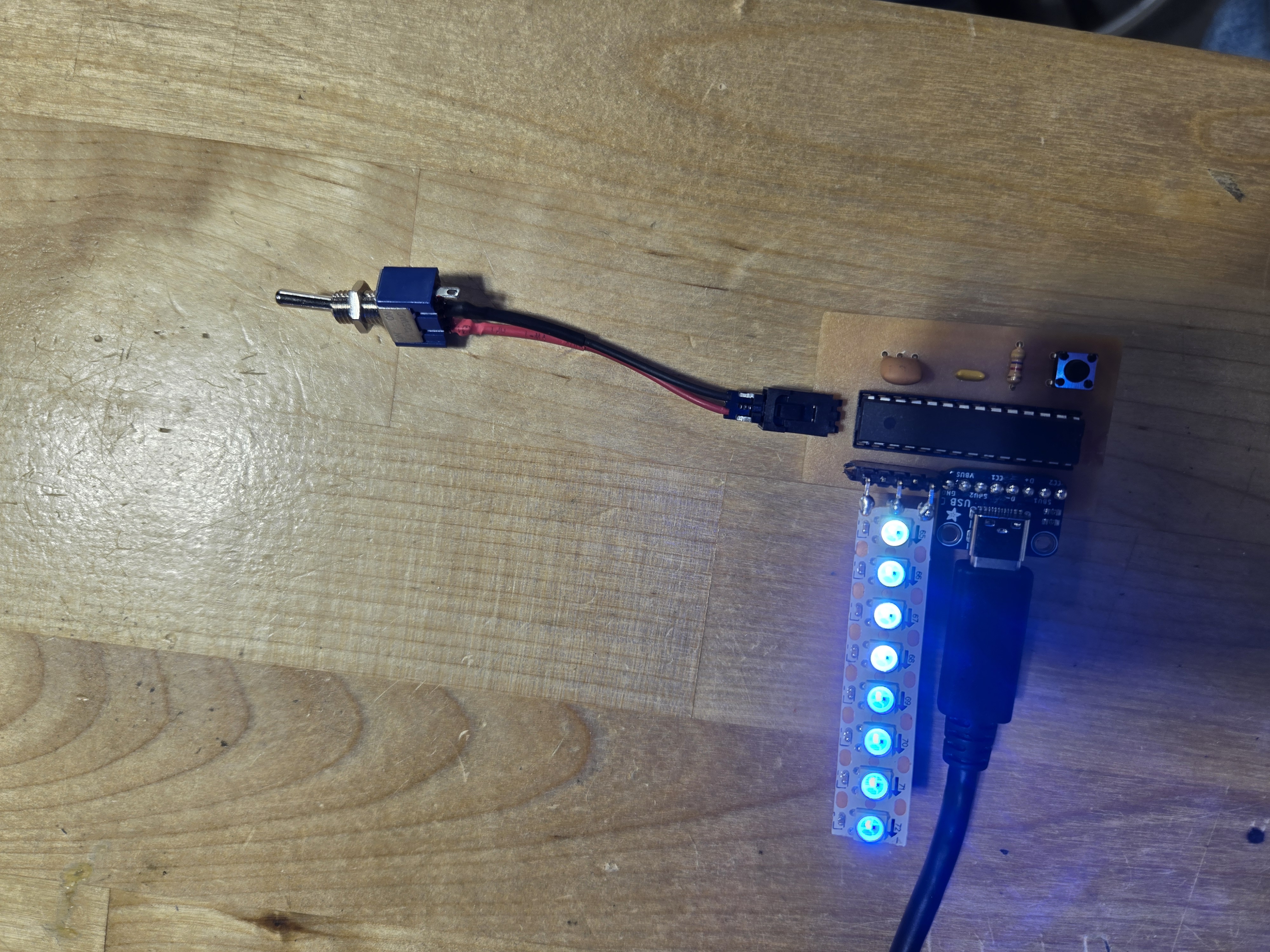
In frustration, I threw my PCB on the table. And then… the light started working! I realized that the light strip connection had a problem – it needed to be bent in a specific way to make contact. As a temporary fix, I bent it to the right position.
But when I decided to resolder it permanently, something went wrong and the light stopped working again. At that point, I decided to create another board from scratch. While I was at it, I also decided to change my switch to act as a software-controlled switch instead of a hardware one.
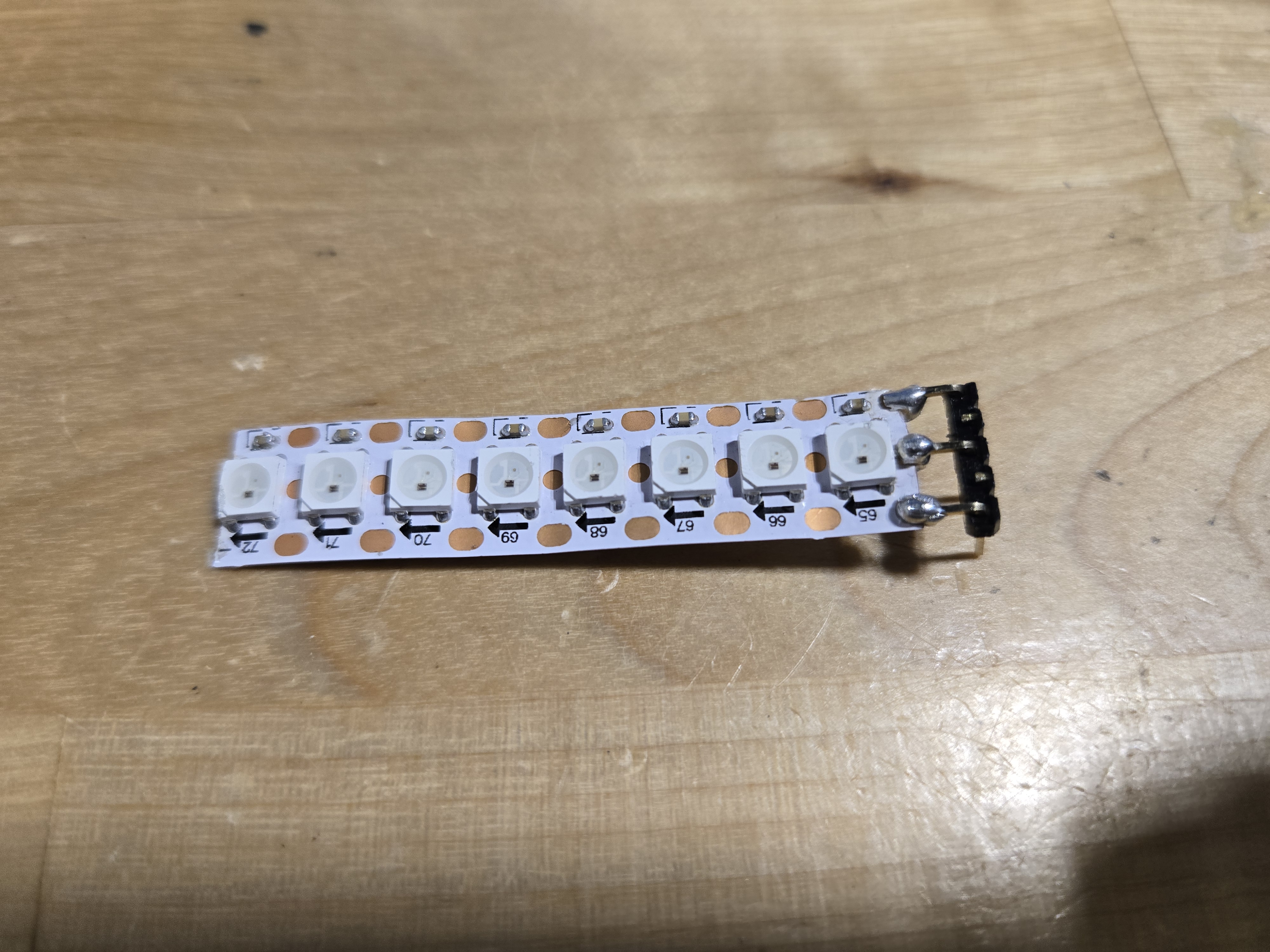
The culprit
Software Control
For the new design, I implemented software control over the LED. Instead of the switch directly controlling power to the LED, it now sends a digital signal to the microcontroller. I used digital read pins to detect when the switch is pressed and toggle the LED on or off accordingly. This gives me much more control and flexibility over the behavior of the lightbox.
The Code
Here’s the actual code I used for controlling the LED light strip with Adafruit NeoPixel:
The code uses the Adafruit NeoPixel library to control a WS2812B LED strip. When the switch (pin 2) reads HIGH, the LEDs turn off. When it reads LOW, each pixel is set to a different color, creating a gradient effect from green to blue. The
pixels.show()call updates the display with the new colors.Next Steps
With the lessons learned from this week, I’m building a new PCB with better traces and proper switch integration. Hopefully, this version will work reliably!
As you can see, there is so much happening in the shop. Thanks for reading!

You must be logged in to post a comment.