
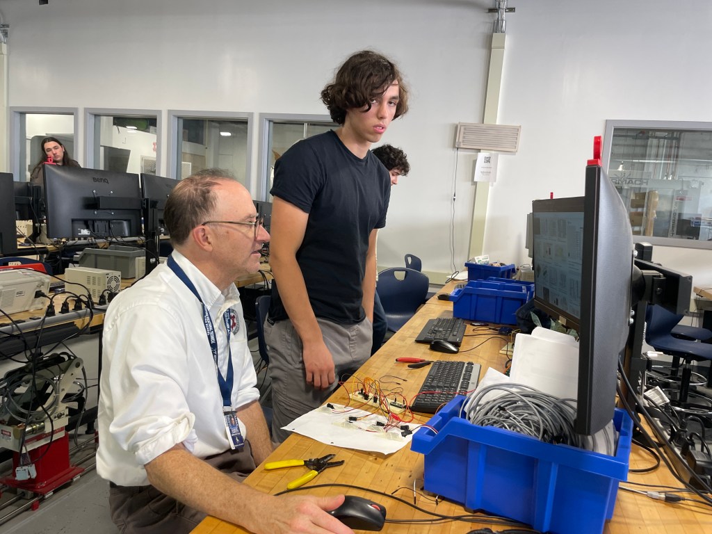
This week we welcomed prospective middle school students into the shop for Open House night on Thursday. Several students helped guide parents around our shop and show them the great work being done. Thank you to Aaron BenDaniel, Echo Valdez-Melgar, Milo Austin, Tanzarul Azam, and Ben Wirz for working late on a school night.
This week Junior Harlan Doeg continued his remote control hand project. He writes on his blog:
I began this week by overhauling the code that I had written originally to control my robotic hand, using arrays to clean up and make my code easier to both read and edit.
this is my code before I edited it:
INCLUDE
Servo myservo1;
Servo myservo2;
Servo myservo3;
Servo myservo4;
Servo myservo5;int pos1 = 0;
int pos2 = 0;
int pos3 = 0;
int pos4 = 0;
int pos5 = 0;void setup() {
myservo1.attach(2);
myservo2.attach(3);
myservo3.attach(4);
myservo4.attach(5);
myservo5.attach(6);Serial.begin(9600);
}void loop() {
pos1 = analogRead(A1);
pos2 = analogRead(A2);
pos3 = analogRead(A3);
pos4 = analogRead(A4);
pos5 = analogRead(A5);pos1 = map(pos1, 540, 770, 0, 180);
pos2 = map(pos2, 540, 770, 0, 180);
pos3 = map(pos3, 540, 770, 0, 180);
pos4 = map(pos4, 540, 770, 0, 180);
pos5 = map(pos5, 540, 770, 0, 180);if (pos1 < 30) pos1 = 0;
if (pos2 < 30) pos2 = 0;
if (pos3 < 30) pos3 = 0;
if (pos4 < 30) pos4 = 0;
if (pos5 < 30) pos5 = 0;Serial.println(pos1);
Serial.println(pos2);
Serial.println(pos3);
Serial.println(pos4);
Serial.println(pos5);myservo1.write(pos1);
myservo2.write(pos2);
myservo3.write(pos3);
myservo4.write(pos4);
myservo5.write(pos5);delay(100);
}and this is my code after I cleaned it up:
INCLUDE
int x;
Servo servo[5];
const byte servoPins[5] = {2, 3, 4, 5, 6};
int pos[5] = {0, 0, 0, 0, 0};void setup() {
Serial.begin(9600);
for (x = 0; x < 5; x++) {
servo[x].attach(servoPins[x]);
}
}
void loop() {
for (x = 0; x < 5; x++) {
pos[x] = analogRead(x);
pos[x] = map(pos[x], 540, 770, 0, 180);
if (pos[x] < 30) pos[x] = 0;
Serial.println (pos[x]);
servo[x].write(pos[x]);
}
delay(100);
}much better, right? one I finished with that I began separating my code into the code that would read the data from the flex sensors and send it off to the hand, and the code that would receive the data and use it to control the hand.
here are the two sets of code:
Transmitter:
INCLUDE
INCLUDE
INCLUDE
int x;
int pos[5] = {0, 0, 0, 0, 0};
RF24 radio(7, 8);
const byte address[10] = “00001”;
int pot = A0;void setup() {
Serial.begin(115200);
radio.begin();
radio.openWritingPipe(address);
radio.setPALevel(RF24_PA_MIN);
radio.stopListening();
}void loop() {
for (x = 0; x < 5; x++) {
pos[x] = analogRead(x);
pos[x] = map(pos[x], 540, 770, 0, 180);
if (pos[x] < 30) pos[x] = 0;
Serial.println (pos[x]);
radio.write(&pos[x], sizeof(pos[x]));
}
delay(100);
}Receiver:
INCLUDE
int x;
Servo servo[5];
const byte servoPins[5] = {2, 3, 4, 5, 6};
int pos[5] = {0, 0, 0, 0, 0};void setup() {
Serial.begin(9600);
for (x = 0; x < 5; x++) {
servo[x].attach(servoPins[x]);
}
}
void loop() {
for (x = 0; x < 5; x++) {
pos[x] = analogRead(x);
pos[x] = map(pos[x], 540, 770, 0, 180);
if (pos[x] < 30) pos[x] = 0;
Serial.println (pos[x]);
servo[x].write(pos[x]);
}
delay(100);
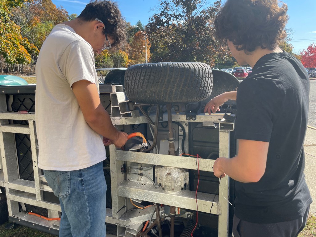
}Next I began to wire the NRF24s and the robotic hand/glove controller together, which can be seen bellow:
After finishing with the wiring I began creating the PCBs, designing the robotic hands PCB on Wednesday which can be seen below:
and then the glove controller PCB on Thursday:
See photos of his progress on his website. Click here to view.
Senior Isaiah Bell continued working on his drone project. It’s taken a lot of effort, but he is making some progress. He writes on his blog:
This week was essentially about fixing the hardware issues from the drone. I am not entirely sure what happened to the ESCs of the drone considering that I have yet to fly the drone. This issue appeared as soon as I accessed the web interface and I noticed that only two of the motors stopped operating when I armed the drone to fly. The goal was to replace the 2nd ESC with a spare that I have in an extra box and to solder those ESC’s to the PDB. Then, I had to check for continuity on the spare’s port to ensure operation. Once, I noticed that the Clean-Flight configurator cleared the 2nd and 3rd ESCs for responsiveness, I knew that this drone was set for flying. My favorite part was connecting to the web interface again and armed the drone again to see if they spun proportionally. Also, I had to test to see if the drone would operate without the ethernet cable.
This is a close up of the PDB and I had to be conscientious of the ports because soldering any of the ports would have destroyed the entire thing. There are many parts that make up the functionality of the drone, but this PDB is THE reason why it can take off from the ground. This part converts power into a smaller circuit that allows current to flow fluently.
I believed that the LiPro Balance Charger will safely charge my new LiPo Battery at a moderate pace. This will avoid making my battery exploded into flames and burning everything flammable in range. This battery must be taken care with extreme caution in order to ensure safe measures.
I also created a highly textured planar surface for the drone because it autonomously uses the RaspiberryPi camera to stay on top of this is surface (Well, this is what it is supposed to do). Since I had yet to fly the drone, this will be the last step after PID tuning for this drone.
He provides some nice photos of his work on his website. Click here to view.
The Sophomore class continued CAD work this week and completed a 1 Pt Perspective hand drawing as part of the Technical Drawing Series.


You must be logged in to post a comment.